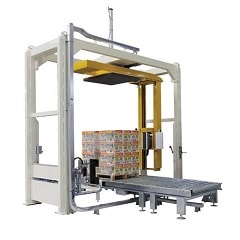
How to Plan a Safe & Efficient Steel Coil Wrapping Machine Layout
Avoid costly installation errors in your steel coil packaging line. This layout guide explains how to map coil journeys, interface equipment, handle buffers, and establish safe operator access.

Steel Coil Wrapping Machine Layout Planning Guide
Steel Coil Wrapping Machine Layout Planning Guide
Plan the work around the coil, the people who handle it, and the situations in which normal flow stops. The wrapper footprint is only one layer of the layout. A usable plan also makes transfer routes, operator access, maintenance access, controlled zones, buffers, utilities, and recovery paths visible before equipment is installed.
The most reliable starting point is a drawing of the current coil journey—not a product outline dropped into an empty floor plan.

Begin with the Coil Journey and the People Around It
Trace one coil from its arrival point through packaging, inspection, release, and its next destination. Beside that material path, trace the operator's work route and the maintenance route. Then ask where the coil can wait safely when the next step is unavailable.
This first pass reveals conflicts that a machine outline misses: a transfer route that crosses an operator position, an inspection task with no safe standing area, or a recovery movement that passes through an active zone.

Build the Layout in Five Layers
Use the same drawing, but review it in layers. Each layer answers a different question and prevents one decision from hiding another.
1. Flow
Where does the coil arrive, pause, enter the wrapping station, receive any inspection, and leave? Mark direction, orientation, ownership at each handoff, and the condition needed for transfer. The line should have a defined response when a downstream station is blocked.
2. Equipment and Transfer Envelope
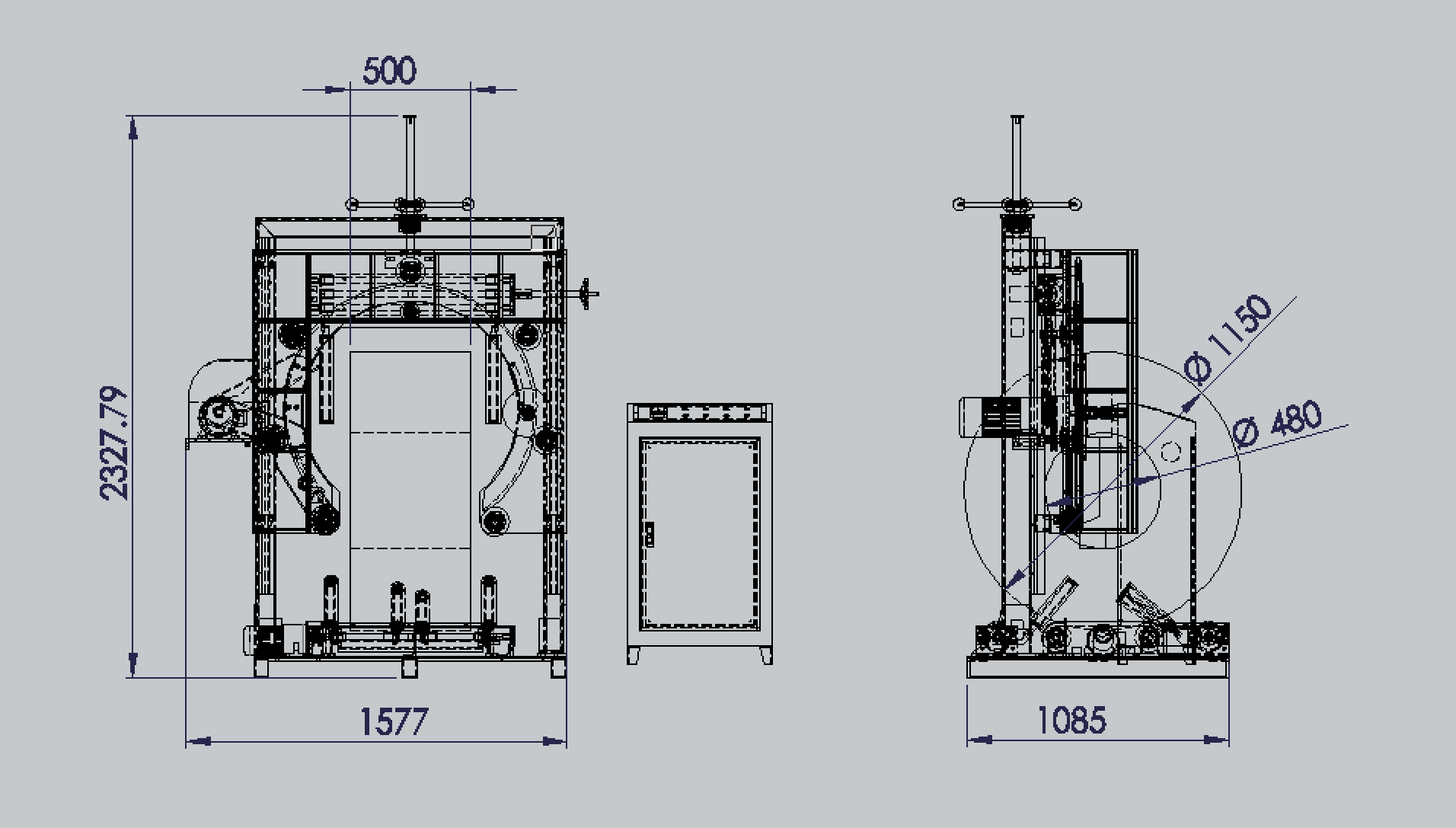
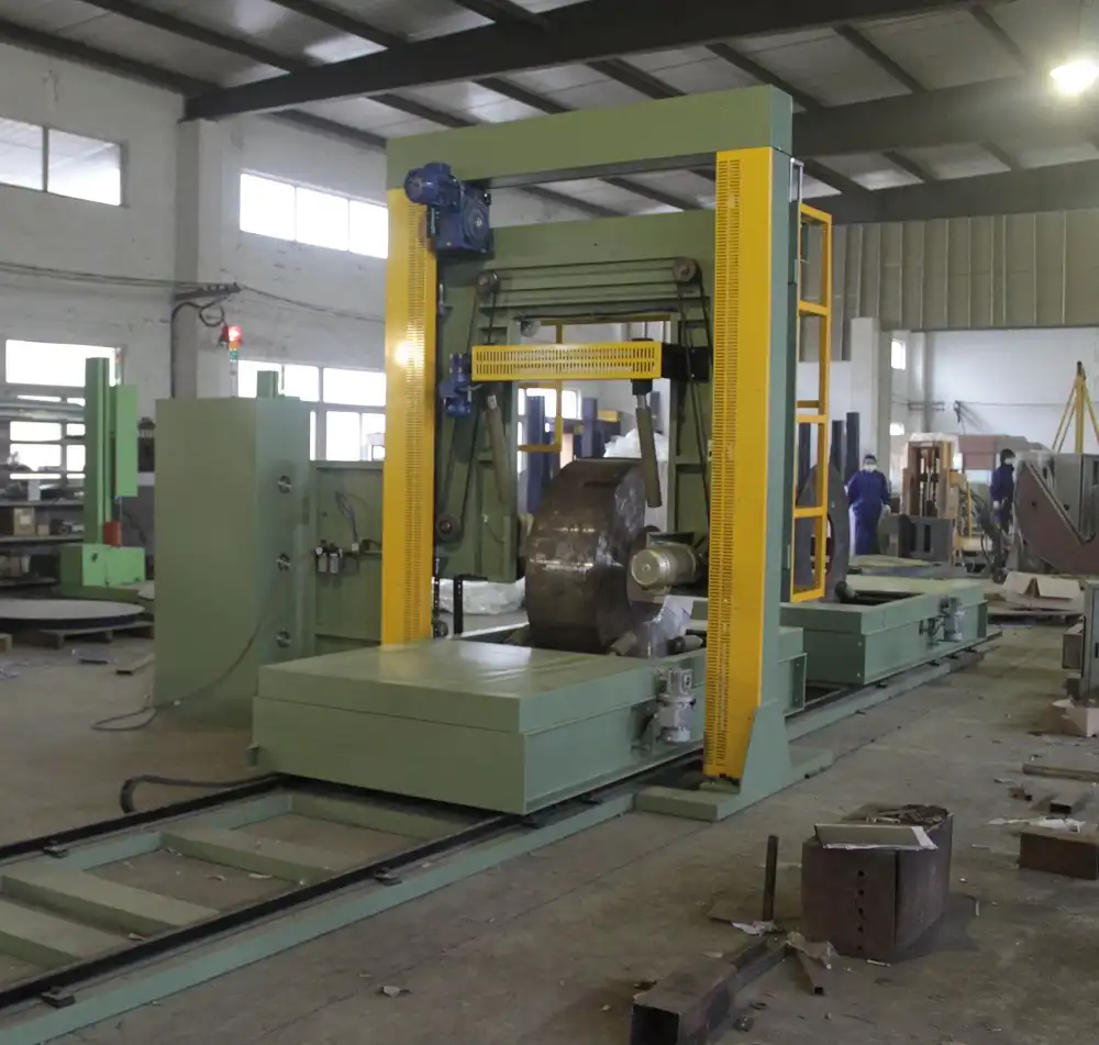
Show more than the machine base. Include the maximum coil envelope, guarding, moving transfer equipment, loading/unloading positions, access doors, and the space required to open, move, or remove service items. Use controlled drawings for dimensions; never infer a clearance from a marketing image.
3. Operation
Mark where an operator supplies material, confirms a process step, inspects a package, and communicates with adjacent stations. If an operation requires a person to stand in a transfer or moving zone, the workflow needs redesign or qualified review before it becomes a drawing instruction.
4. Service
Identify how maintenance reaches drives, sensors, controls, material paths, and wear items. Service access is not spare floor area: it needs a deliberate route, an isolation and work boundary defined by the applicable project controls, and a realistic way to handle removed parts.
5. Safety and Recovery
Identify controlled access, safeguarding boundaries, emergency-stop responsibility, and the point at which the system hands control to another station. Then draw the abnormal path: a misaligned, damaged, incomplete, or stopped coil must have a safe holding and recovery route that does not depend on passing through moving equipment.
Choose Interfaces by the Work They Must Perform
"Crane," "trolley," "conveyor," and "upender" describe different transfer roles, not interchangeable layout labels. The current product taxonomy groups an upender with a tilter, tipper, or turner: it changes the coil's orientation. A crane, trolley, or conveyor may instead deliver, position, or release the coil. The layout review needs the actual sequence, responsibilities, limits, and confirmations—not just the equipment names.
| Interface | Layout Question to Answer | Evidence Needed Before Final Design |
|---|---|---|
| Crane | Can the lift path, hook approach, parking position, and transfer handoff be completed without conflicting with the station or people route? | Current lifting plan, coil lifting method, building/overhead constraints, and responsible review. |
| Trolley | Where does it start, stop, buffer, and release the coil, and what confirms it is clear to move? | Track/transfer drawing, stop logic, interface responsibility, and abnormal-position plan. |
| Conveyor | Are height, coil support, spacing, transfer condition, buffer behaviour, and control signals compatible across the boundary? | Controlled interface drawing, load/support data, controls matrix, and acceptance method. |
| Upender/tilter | Where does orientation change, who controls that step, and how is the changed posture contained through the next handoff? | Equipment envelope, coil range, safeguarding boundary, sequence review, and recovery procedure. |
The comparison is deliberately not a selection ranking. An interface can be suitable only when the product, site, adjacent equipment, and operating method have been confirmed together.
Make Buffers and Abnormal Recovery Explicit
A buffer is a planned place for a coil to wait with a stated condition and owner. It is not an unlabelled empty area on a drawing. Define its entry and release conditions, maximum intended queue, inspection responsibility, and what happens if it is unavailable.
Also test the layout against predictable interruptions: a coil that cannot transfer, packaging material that cannot be fed, loss of a downstream release, a failed confirmation, or a package that does not meet the acceptance check. Do not publish or approve a recovery instruction from this article; use the site's approved procedures and qualified review for the actual system.
Put Utility and Control Boundaries on the Drawing
Show where required services enter the equipment boundary, where control responsibility changes, and which signals or confirmations must cross an interface. The public article does not prescribe voltage, air demand, network protocol, foundation, safeguarding, or functional-safety requirements because those must come from the applicable machine documents, site conditions, and qualified project review.
This boundary map is valuable even at concept stage. It turns "integration" into a list of named decisions that engineering, maintenance, automation, and the supplier can check.
Review the Layout Before It Becomes a Commitment
Use three review gates:
- Concept review: confirm scope, coil journey, preliminary interfaces, operator route, buffer and abnormal-recovery concept.
- Detailed interface review: confirm controlled drawings, envelopes, utilities, controls, responsibilities, assumptions, exclusions, and acceptance evidence.
- Pre-installation and commissioning review: confirm measured site conditions, approved safety and operating controls, revisions, training/ownership boundaries, and the test record required for handover.
Each gate should record the drawing revision, participants, decisions, open items, and the condition that closes each item. A drawing without those records may be useful for discussion, but it is not proof that an installation is ready.
A Practical Next Step
Take the latest site drawing and trace one normal coil and one abnormal coil through it with production, maintenance, controls, and safety representatives. Mark every handoff, standing position, service route, buffer, utility boundary, and open assumption. Give each open item an owner and closure test before asking for a final equipment layout or installation commitment.
Visual Details
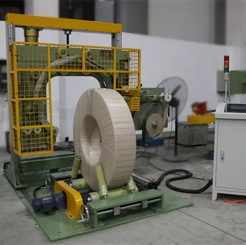
Click to enlarge

Click to enlarge
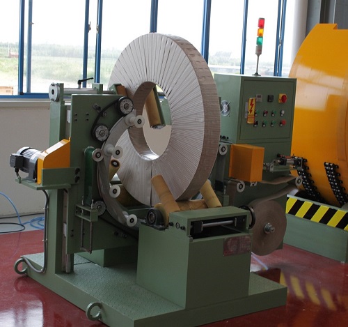
Click to enlarge
Click to enlarge
Watch How It Works
Discover how our automated packaging solutions optimize your production line efficiency. This video demonstrates the seamless operation designed for maximum protection.
Trusted by Steel Mills & Industry Leaders
Global manufacturers rely on FHOPE heavy duty packaging equipment


Ready to optimize your packaging line?
Get a custom quote with ROI analysis. Our engineers respond within 24 hours.
- Free layout design
- Global installation support
- 2-year warranty included
Your information is secure and will never be shared.
Related Machines
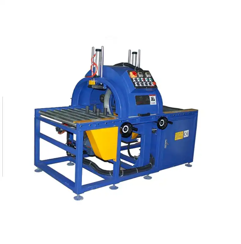
E100 Horizontal stretch wrapping machine
View Details →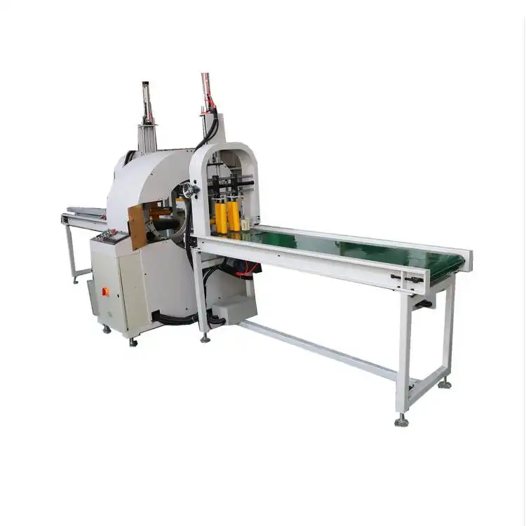
E200 Horizontal stretch wrapping machine
View Details →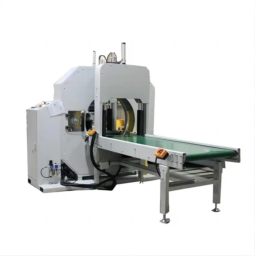
E300 Horizontal stretch wrapping machine
View Details →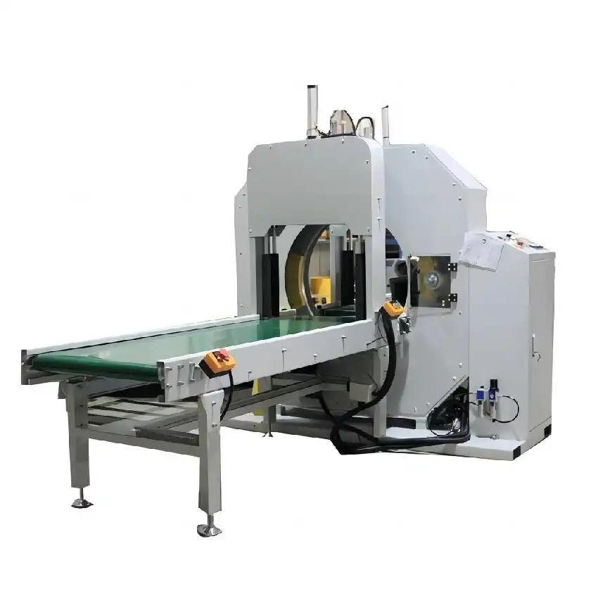
E400 Horizontal stretch wrapping machine
View Details →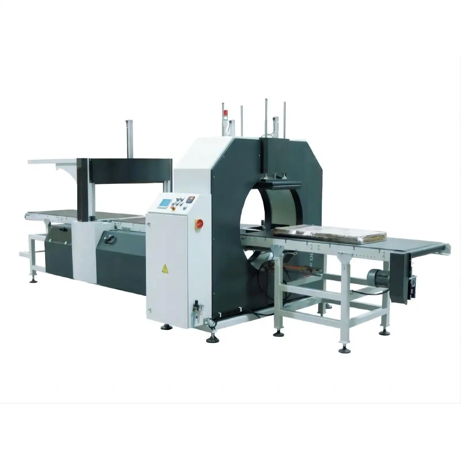
E500 horizontal wrapping machine&stretch wrapper
View Details →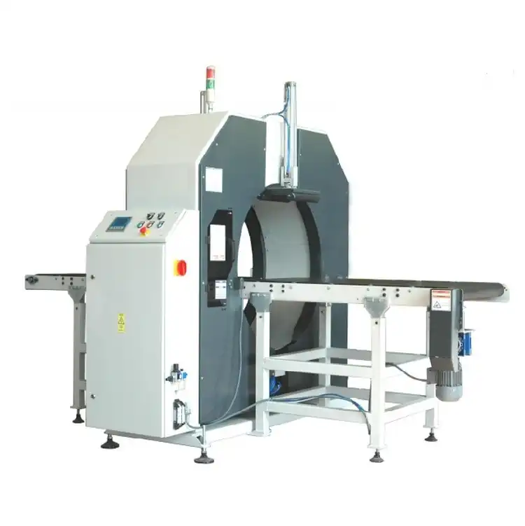
E600 Horizontal stretch wrapping machine
View Details →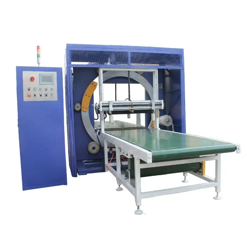
E1000 Horizontal stretch wrapping machine
View Details →
E1400 Horizontal stretch wrapping machine
View Details →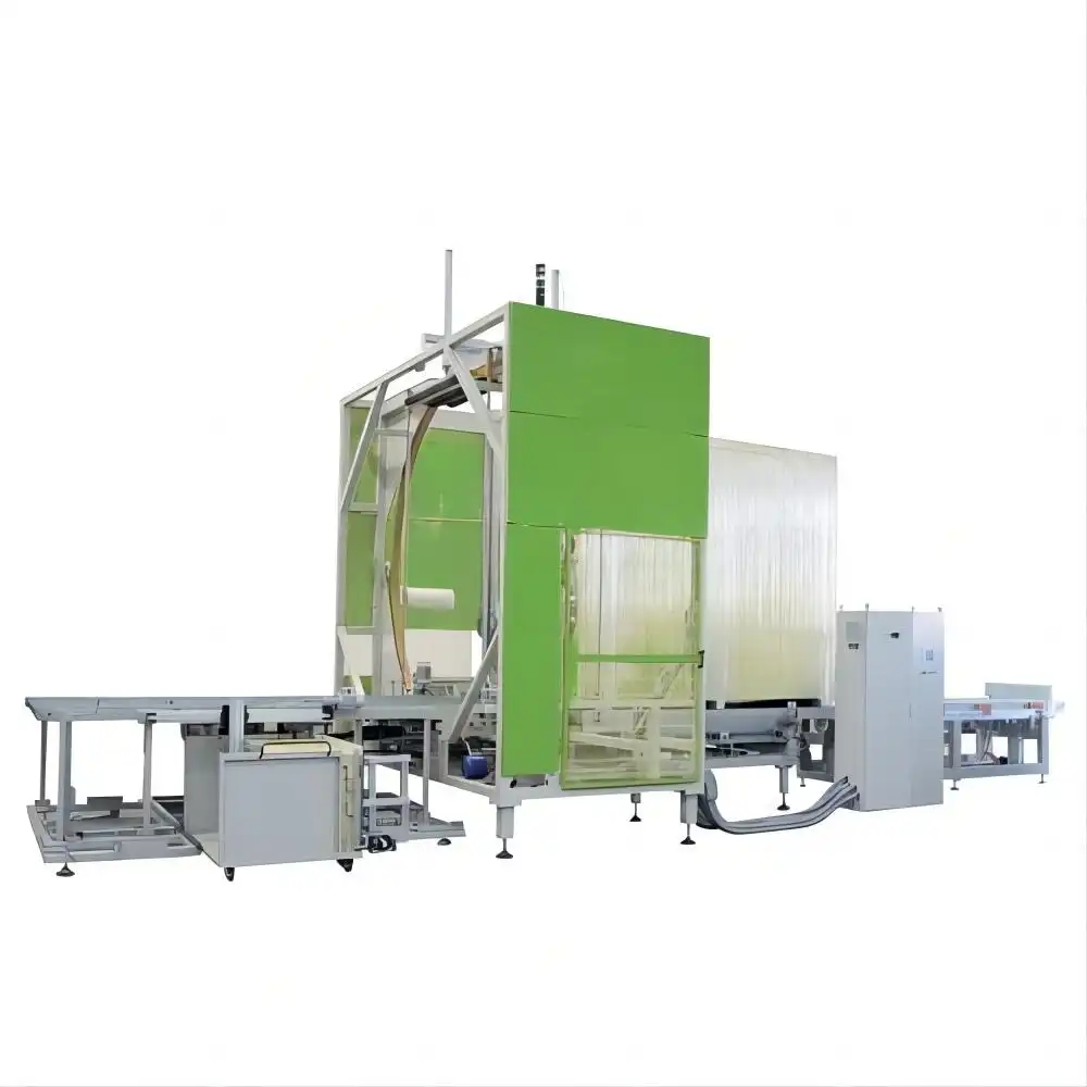
E2400 Horizontal stretch wrapping machine
View Details →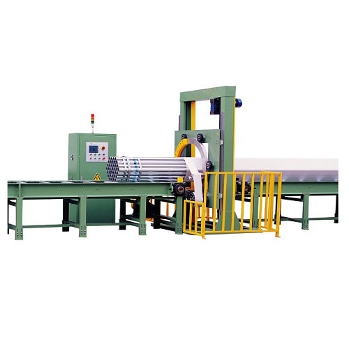
Pipe Horizontal Orbital Wrapping Machine
View Details →
Horizontal Orbital Wrapping Machine for rod and bar
View Details →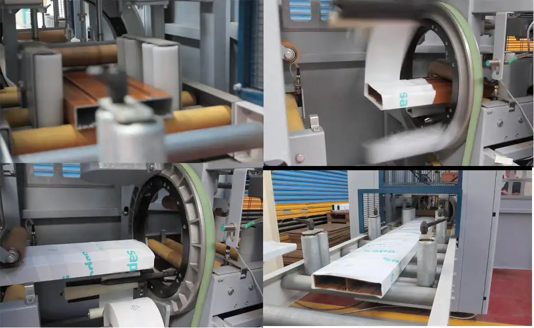
Aluminum Horizontal Orbital Wrapping Machine
View Details →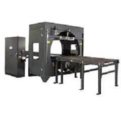
Profile Horizontal Orbital Wrapping Machine
View Details →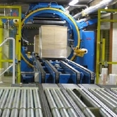
Horizontal Stretch Wrapping Machine for pallet
View Details →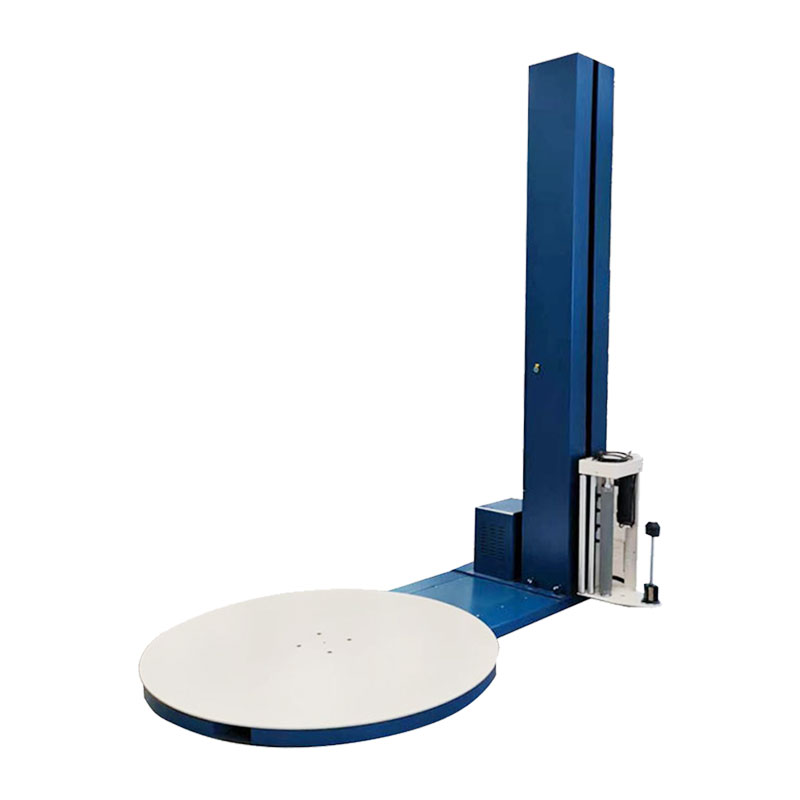
Pallet Stretch Wrapping Machine-A100
View Details →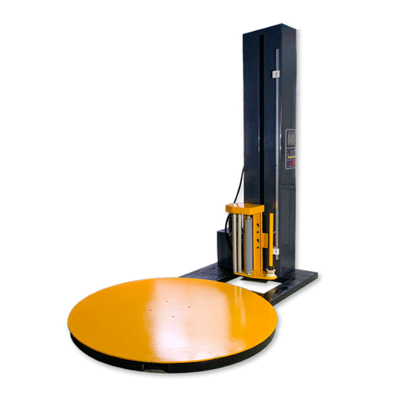
Pallet Stretch Wrapping Machine-A200
View Details →
Pallet Stretch Wrapping Machine-A400
View Details →
Pallet Stretch Wrapping Machine M-type
View Details →
Automatic Stretch Wrapping Machine B200
View Details →